

XCMG official 18m mobile hydraulic articulated boom lift GTBZ18A1 aerial work platform for sale



Description
Recommendation
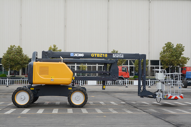
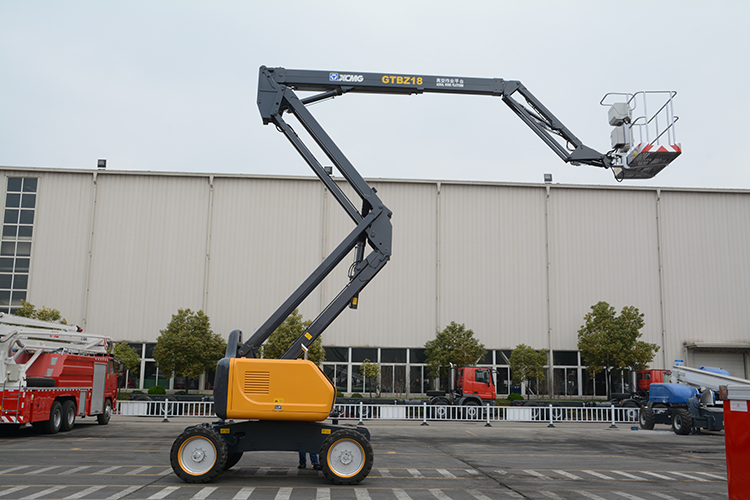
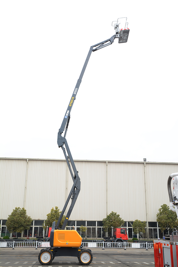
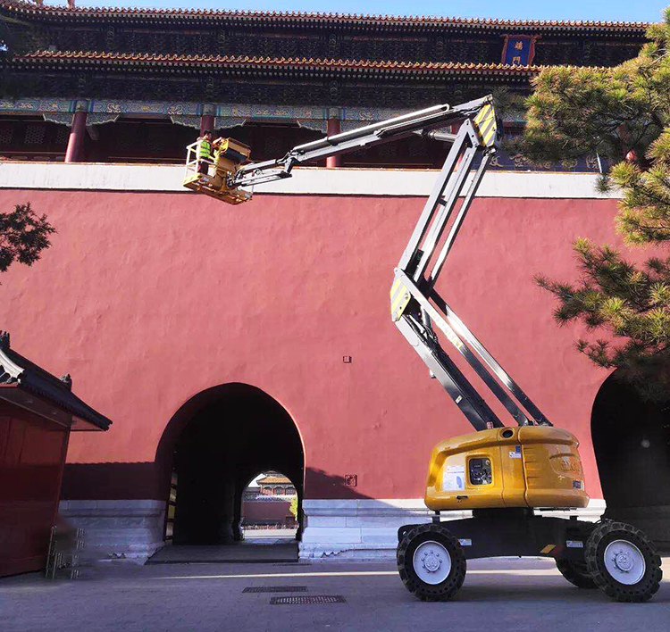
18m mobile hydraulic articulated boom lift aerial work
platform GTBZ18A1.
For 18m level “Σ” type linkage folded hybrid boom aerial
work platform, its readability, operating performance and humanization has
reached to the advanced level in the industry.
The linkage folded hybrid arm has compact structure and flexible
stretching, which is easy to get to the unreachable areas; with four-wheel
drive, off-road wide tires and axle balancing device, the equipment has
excellent drive and terrain adaptability.
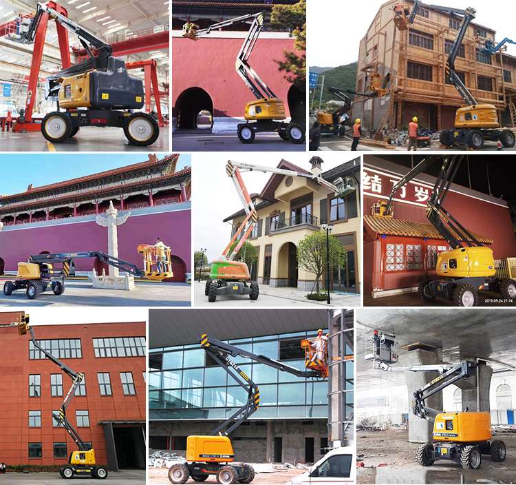
The model manipulation is simple, safe, reliable, accurate
and efficient, which can meet the requirements of the construction,
petrochemical, venues, leasing and other industry users.
Advantages and highlights:
1.The undercarriage assembly
The running mode is subject to hydraulic driving, and the
driving mode adopts four-wheel drive; besides, it has also selected the
built-in running reducer integrating motor and reducer, and set fast and slow
speed gears of driving speed, which can meet the driving requirements of
vehicle under different environments. When driving on slopes, the running
mechanism possesses self-braking function; meanwhile, it is also set with
clutch device, which can facilitate dragging, in case of any faults.
2.Arm rest assembly
The aboard combined arm assembly refers to the folded arm
+ telescopic arm + one section of crank arm.
3.Rotary table
The rotary table is set as per hinge joints of single
stiffened plate, and the counterweight is set behind it. With respect to the
counterweight, fuel tank, hydraulic oil tank and control cabinet are set on the
left side of the rotary table; the engine and accumulator are set on the right
side of the rotary table.
4.Hydraulic system
Two-pump drive is adopted for the hydraulic system, and it
is formed through the series connection of variable displacement piston pump
and constant displacement pump, and the direct drive of the engine will provide
power for the hydraulic system.
5.Electrical system
Distributed PLC control technology is adopted for the
electrical system, and the controllers are set on the platform and rotary table
respectively. The rotary table and platform controller are communicated via CAN
bus. Rotary table and platform were set up control box to achieve the control of
chassis, rotary table, boom and platform.

|
Item |
Unit |
Parameter |
|
a. Overall length |
mm |
9080 |
|
b. Overall width |
mm |
2490 |
|
c. Overall height |
mm |
2680 |
|
d. Wheelbase |
mm |
2500 |
|
Maximum working height |
m |
20.3 |
|
Maximum platform height |
m |
18.6 |
|
Maximum working range |
m |
11.9 |
|
Maximum load weight |
kg |
230 |
|
No.1 arm luffing range |
° |
0 ~ +70 |
|
No.2 arm luffing range |
° |
0 ~ +75 |
|
Crank arm luffing range |
° |
-65 ~ 70 |
|
The swing angle of the rotary table |
° |
360 |
|
Maximum tail wagging |
mm |
0 |
|
Platform size |
mm |
1830×760×1150 |
|
The swing angle of the platform |
° |
180 |
|
Machine weight |
kg |
10600 |
|
Maximum travelling speed |
km/h |
6.0 |
|
Minimum turning radius |
m |
6.0 |
|
Minimum ground clearance |
mm |
230 |
|
Maximum gradeability |
% |
45 |
|
Type size |
355/55D625 |
|
|
Motor model |
Perkins 404D-22 |
|
|
Rated power of motor |
kW/(r/min) |
38KW/3000rpm, |

.jpg)
- 1、Select the Clip Coupon button
- 2、Add 1 item from the products below to your Cart using the Add to Cart button or select See Options for specific product variations.
- 3、ITEMdetails.WhenyouredoneshoppingselectGotocart
* Description
 Add Attachments
 Home
Home
 Categories
 Discover
 My Machmall


